
Understanding IPv4 Addressing and Address Classes
IPv4 has been in use since the start of the Internet, and is widely deployed across the Internet, and home networks.
In this tutorial we will cover the basics of IPv4 Addresses.
You will Learn
- IPv4 address structure
- IPV4 Address classes
- Special and reserved IP addresses
- Broadcast Vasics
IPv4 Addresses and Structure
IPv4 uses 32 bits for addressing. The 32 bits are split into 4 bytes and each byte is separated by a dot(.). So it is of this form:
a.b.c.d
Where the value of a,b,c or d is between 0-255 decimal. A typical IP address appears like this:
192.168.0.1
Networks and Nodes
An IP address has two components- A network component, and a node component.
As an Analogy if you think of the address of your house it is of the fo
House Number + Street name e.g 12 King Street.
For computer networks the network number is equivalent to the street name and the house number is the Node Address.
The earlier implementation of IPv4 used address classes to divide the address space into network and node components.
This arrangement was very wasteful of IP addresses and was discontinued, but the terms Class A, B and C networks are still used.
IP4 Address Classes
The address classes divide the address space into addresses that support:
- Large numbers of nodes – Intended for a large organisation – Class A addresses
- Medium number of nodes- Class B addresses
- Small number of nodes- Intended for a small organisation –Class C addresses
For Example Class A addresses would be used by large organisations (e.g. IBM) which had lots of computers (nodes) and so would require a large number of node addresses.
Because there would only be a small number of large organisations then there would only be a small number of class A networks.
A class A address uses 8 bits for the network Address and 24 bits for node addresses. We can write this as:
Net.Node.Node.Node
Therefore there can only be 256 (28) Class A networks but each network can have 16,777,216 (224) nodes.
Class B network addresses were for medium sized organisations and used 2 bytes (16 bits) for the Network and 2 bytes for node addresses.We can write this as:
Net.Net.Node.Node
Class C network addresses were for small organisations and used 3bytes for the Network and 1 byte for node addresses.
Net.Net.Net.Node
Class D and E are reserved
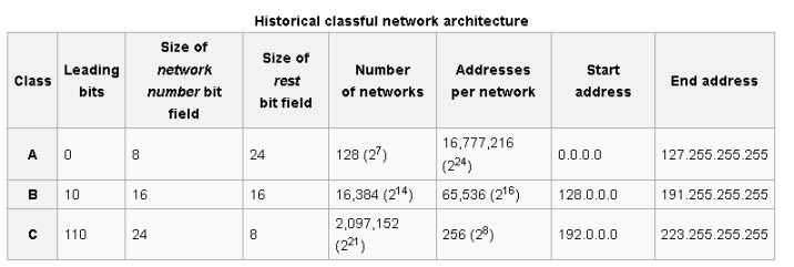
Here is a useful summary table taken from Wiki
How to Distinguish Class A, Class B Addresses
We need a way of distinguishing a class A address from a Class B ,C,D or E address.
The method used was to use the location on the first 0 bit in the the Most significant bits of the first byte. If the first bit is O then we have a class A Address.
The other 7 bits can be either 0 or 1 (shown as X)
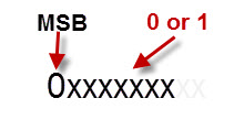
This means that a class A network address is always in the range 0 to 127 – all zeros 00000000, and all ones –01111111 except first 0
With a Class B address the MSB is a 1 and the next one is a 0
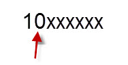
This means that a class B network address is always in the range 128 to 191 – 1000000 and 1011111
With a Class C address the the first two bits are 1’s and the next one is a 0
This means that a class C network address is always in the range 192 to 223 – 1100000 and 11011111
This type of addressing is known as classful addressing and resulted in very wasteful IP address allocation.
It was replaced by a newer method called Classless Inter-Domain Routing (CIDR), .-See RFC 1518 and RFC 1519.
The division between Network and node was accomplished using a technique called subnetting.
Private and Special Addresses
Certain IP addresses are not routable on the Internet and are reserved for Internal networks, they are known as private addresses:
- 10.0.0.0 -Class A address
- 172.16.0.0 through to 172.31.0.0 – 16 contiguous class B networks
- 192.168.0.0 through to 192.168.255.0 –256 contiguous class C networks
All ones and All zeros node addresses – IP node addresses like 192.168.0.0 or 192.168.0.255 are not allowed.
This means that a class C network like 192.168.1.0 has 8 bits for the node giving 28 or 256 possibilities.
However due to the all 1s all 0’s rule then we can only have 254 possible nodes.
127.0.0.1 is commonly known as the loopback address, and is used for testing the local IP address stack. A packet addressed to 127.0.0.1 is not sent onto the network but only the IP software stack.
Th entire 127.0.0.0 network is actually reserved, and so you could use any address in that range e.g. 127.0.0.3 would also work.
The link local address range 169.254.0.0 is used to auto assign IP addresses when no DHCP server available.
Unicast, Broadcast and Multicast Addressing
The most common form of addressing is unicast. In this form a message is sent to a single host using it’s IP address.
A broadcast message is sent to all hosts on a network or subnetwork and is created by setting the the node part of the IP address to all 1’s.
A sender sends a single message and all hosts on the network receive it.
To send a broadcast to all hosts on the Class C network 195.1.1.0 you would send it to address 195.1.1.255.
Note: Broadcasts messages do not go through routers.
Multicasting lets you send message to a group of nodes. To receive a multicast message a node must register its interest. Muticast messages are sent using the Class D address range 224.0.0.0 to 239.255.255.255
Note: Routers are responsible for propagating and copying multicast messages. See Understanding Multicasting
SubNetting
Because of the way networks work having a single network with thousands of hosts isn’t practical.
It is equivalent to have a street with thousands of houses on it. Just imagine trying to get on to the street in the morning to go to work.
Therefore a technique called subnetting was devised that allows you to split a network into smaller networks know as subnets. – Subnets and subnet Masking explained.
Summary
IPv4 addresses use 32 bits are a written using dotted decimal notation. Address classes identify the network and node components of an IP address.

Subnetting and Subnet Masks Explained
What is Subnetting ?-Subnetting is the process of diving a network into small networks and is a common task on IPV4 networks.
Before we discuss how to implement it it is useful to understand why and when we need to do it and to do that we are first going to work through a simple analogy to illustrate the problem subnetting solves
Subnetting Analogy
As an analogy imagine a school and we need to split it into class rooms.
But why split it into class rooms? The answer is to stop classes interfering with one another.
Now each classroom has a desk with a computer and we have been tasked with creating a labeling system for the computers.
Now say we have 30 classrooms each with a maximum of 30 students and computers.
If we assign numbers to our classrooms and computers then we could have for example:
computer 11, classroom 24
We need two digits for the classroom which would allow for a maximum of 100 classrooms (0-99).
We need two digits for the computer which would allow for a maximum of 100 computers (0-99).
If we also say that classroom numbers 0 and 99 and computer numbers 0 and 99 were reserved and not allowed to be assigned then we now have a maximum of 98 classrooms and 98 computers which is enough for own requirements.
So lets create our label we could use the following scheme:
- computer 11, classroom 24
- 24-11
- 11-24
- 2411
- etc
There are many possible permutations we just need to pick one and tell every one about out labeling scheme.
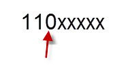
Lets assume we go for 2411 where 24 is the classroom and 11 is the computer.
So now when we see the following 0223 we now know that this refers to classroom 2 and computer 23.
This we do easily in our heads once we know the labelling scheme.
We could even make it easier for ourselves by creating a paper mask that we put over the label that would reveal the classroom.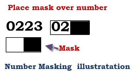
IP Addresses and Subnetting
Just like in our classroom example an IP address is split into two components a network component and a node component.
So the address 10.0.2.1 is split into Network plus Node.
So is the network number 10, or 10.2 or 10.0.2 ?
In early IPv4 networks address classes were used to identify the number of bytes allocated to the network component.
The main classes were class A,B,C. With the allocation as follows:
Class A network,node,node,node
Class B network,network,node,node
Class C network,network,network,node
To determine the class you needed to examine the most significant byte (far left).
- 0-127 Class A
- 128-191 Class B
- 192-ccc Class C
IP Subnetting- Problems with Large Networks
All modern networks use the Ethernet data link protocol.
Ethernet uses a shared media and is negatively effected when a large number of nodes are connected to the same media.
This is just the same as having too many kids in the same classroom.
You can equate a network and node address to our classroom and desk number
What would happen if you had a classroom with 100’s of desks i.e. hundreds of pupils?
So even though a Class A address can accommodate thousands of nodes it it totally impractical to put this many nodes on a single network.
The solution to the problem was to split the network into small networks called sub networks or subnets.
Take for example a class A address which uses 1 byte for the network ID and 3 bytes for the Node ID. Written
Net.Node.Node.Node
It is important to understand that the network part of the address is only used for routing IP packets on the public internet.
Once the packet enters the private network then the Node address is used and the public Network address is not used.
Now a network administrator can interpret the node address any way they want, and so it is possible to split the node address into subnet and Node. So we could have
Net.Subnet.Node.Node or Net.Subnet.Subnet.Node.
The technique used to create subnets is to use a Mask.
The mask effectively hides the Node component and leaves the network and sub network components.
If the IP address was printed on paper we could hide the last byte by placing a paper mask over the number with three holes.
Note: if your binary is a little rusty see the binary numbers tutorial
To do this on a computer we use a number which we then logically AND with with IP address.
Here is the logic table for AND
1 and 1 =1
1 and 0 =0
0 and 1 =0
0 and 0 =0
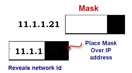
So our mask to hide the last byte is 255.255.255.0 As 0 and Anything is always 0
The best way to see this is to write the numbers out in binary
000001011.00000001.00000001.00010101 = 11.1.1.21
11111111.11111111.11111111.00000000 =255.255.255.0
and then do a logical AND
the Network address is 11.1.1.0 which corresponds to network 11 subnet 1.1
The Subnet mask determines how the IPv4 address is split.
Th example above used a class A IP address we can do the same with a class B address.
Net.Net.Node.Node —->Net.Net.Subnet.Node Using Mask 255.255.255.0
Subnetting on a byte boundary is the easiest to do and understand but we can also subnet on non byte boundaries.
Worked Examples
1- You have been allocated a class A network address of 29.0.0.0. You need to create at least 20 networks and each network will support a maximum of 160 hosts. Would the following two subnet masks Work?
255.255.0.0 and or 255.255.255.0
Yes both would work.
Mask 255.255.0.0 has 8 bits for the subnet and 16 bits for the host
8 bits would accommodate 28=256 subnets
16 bits would accommodate 216= over 64000 hosts
Mask 255.255.255.0 has 16 bits for the subnet and 8 bits of the host.
Have possible 28 -2 hosts =254 which is enough.
2. – You have been allocated a class B network address of 135.1.0.0 and and need to create 4 subnets each with around 200 hosts what is the easiest mask to use to satisfy the criteria?
Easiest is to sub net on a byte boundary which would mean a subnet mask of 255.255.255.0
This would allocate 8 bits for the subnet and 8 bits for the host.
We need to accommodate around 200 hosts which requires 8 bits which we have.
We need 4 subnets which requires 4 bits and we have 8 bits. So we have more than enough.
Classless Inter-Domain Routing (CIDR)
Classless Inter-Domain Routing was introduced in 1993 to replace the classful network design.
Instead of allocating network addresses using address classes based on 8 bit groups it uses variable length subnet masking.
It also introduced a new method of denoting network masks.
Example:
A class C network would have a subnet mask of 255.255.255.0 which means that 24 bits are used for the network.
In CIDR notation this is designated by a /24 following the IP address. So:
IP address 192.168.1.168 subnet mask 255.255.255.0 is written as: 192.168.1.168/24 in CIDR notation.
| Address Class | No of Network Bits | No of Host Bits | Subnet mask | CIDR notation |
| A | 8 | 24 | 255.0.0.0 | /8 |
| A | 9 | 23 | 255.128.0.0 | /9 |
| A | 12 | 20 | 255.240.0.0 | /12 |
| A | 14 | 18 | 255.252.0.0 | /14 |
| B | 16 | 16 | 255.255.0.0 | /16 |
| B | 17 | 15 | 255.255.128.0 | /17 |
| B | 20 | 12 | 255.255.240.0 | /20 |
| B | 22 | 10 | 255.255.252.0 | /22 |
| C | 24 | 8 | 255.255.255.0 | /24 |
| C | 25 | 7 | 255.255.255.128 | /25 |
| C | 28 | 4 | 255.255.255.240 | /28 |
| C | 30 | 2 | 255.255.255.252 | /30 |
Worked Examples
- Write the IP address 222.1.1.20 mask 255.255.255.192 in CIDR notation
Decimal 192 =11000000 binary which means that 2 bits of this octet are used for the subnet. Now add the 24 bits 255.255.255 and we have 26 bits. So we write:
222.1.1.20/26
2. Write is the IP address 135.1.1.25 mask 255.255. 248.0 in CIDR notation
Decimal 248 =11111000 binary which means that 5 bits of this octet are used for the subnet. Now add the 16 bits 255.255. and we have 21 bits. So we write:
135..1.1.25/21
Simple Subnetting Exercise Questions
The best way to learn to do subnetting is to try some examples. We will look a some common subnetting problems that arise when creating networks.
1 – You have been allocated a class C network address of 201.1.1.0 how may hosts can you have?
2- You have been allocated a class A network address of 21.0.0.0. You need create at least 10 networks and each network will support a maximum of 100 hosts. Would the following two subnet masks Work.
255.255.0.0 and or 255.255.255.0
3 – You have been allocated a Class B network address of 129.1.0.0. You have subnetted it using the subnet mask 255.255.255.0 How many networks can you Have and how many hosts can you place on each network?
Answers
A1– 256-2= 254 – Why? host addresses of all 0’s and all 1’s are not allowed.
A2- Yes you only need 8 bits for 100 hosts and both subnet masks would give you that.
A subnet mask of 255.255.255.0 would give you lots of networks (2 16) and 254 hosts.
A subnet of 255.255.0.0 would give you lots of hosts (approx 216) and 256 networks.
A3 – the network has 8 bits and so does the node component. This means that you have have 28 =256 networks and 256 -2 = 254 hosts
Subnetting Class C Addresses
So far we have been subnetting on a byte boundary using class A and B addresses.
Now we are going to look at how we subnet on a non-byte boundary using a Class C Address.
Exercise- You have been allocated a class C network address of 195.1.1.0.
You need to create 5 sub networks each network has a maximum of 10 hosts.
Now our current subnet mask is 255.255.255.0
We can only use the first 8 bits for out subnets as these 8 bits have been allocated as host addresses.
So for 10 hosts we need 4 bits (16-2 =14 hosts)
for 5 subnets we need 3 bits (8 networks possible)
possible masks:
11100000=224 (Note: 3 bits for sub networks)
11110000=240 (Note: 4 bits for sub networks)
So Subnet masks of 255.255.255.224 and 255.255.255.240 would both work.
In CIDR notation we have 195.1.1.0/27 and 195.1.1.0/28
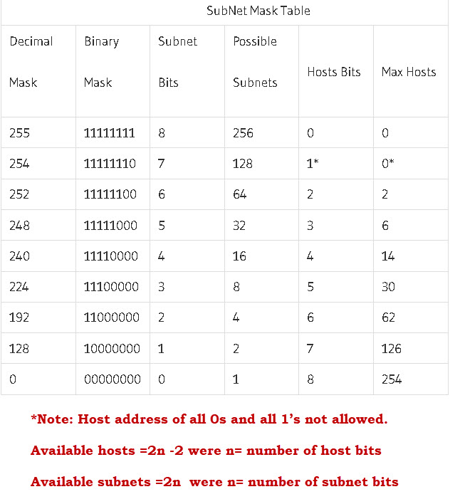
Subnet Table and Calculator
Below is a simple subnet table that makes it easier for calculating subnets.

Ip Subnet Mask and IP Address
IP address subnetting is a visible way in which to breakdown networks into sub networks with an IP address.
The purpose of IP addressing subnet is to prevent collisions in packet transfers from one networked item to the next. In an IP address you can find on https://www.ip-locations.org/ there is four octets of numbers separated by periods (192.168.0.1), each octet representing 8 bits. In these eight bits the numbers range from zero to two hundred and fifty five bytes.
In order for information to be passed from one pc to another, there has to be a portion of octets in the IP address devoted to the network and another part devoted to the host for connectivity between the two.
How to Setup Ip address subnet mask
In order to properly subnet an IP address we would have to know how many hosts we are looking to add to our network always being aware that the first and last bit in your subnetted IP address are taken for use with the network and host as I mentioned above for communication.
Once we have determined the number of hosts we have to be aware of what IP address class our IP address will fall under.
For most offices and business intranets there is a subnet class A address used.
There are three Ip address classes A ,B and C.
These subnet classes confirm your default Ip address subnet mask.
Once you confirm your Ip subnets mask you can then begin to subnet.
The four octet’s breakdown in to eight bits, these eight bits have their own value from zero to one hundred and twenty eight.
There is a rule here as half of the octets are reserved for the network and the other half for the host.
Now that the Ip address subnet mask is confirmed from right to left giving each 8 bits a value starting with 128 de-incremented in half for the remaining 7 bits, 128, 64, 32 etc.
The next part to IP subnetting is choosing your number of host’s, the network and host portion of the octets range in value of two bits to two hundred and fifty six bits.
These values are also incremented in half by themselves.
Make sure when choosing the number of hosts that you leave the two bits needed for the network and host.
From this information given you can subnet your IP address and determine the custom Ip subnetting mask of your IP address.
